English Sitemap
Home
Cuee
People
Research
Education
Events
Outreach
Publication
Partnerships
Openings
Link
Internal

 ■ Damage of Shinkansen Viaduct

Kawashima, K., Watanabe, G. and Lee, T. Y., Nagata, S. and Sakellaraki, D.
Department of Civil Engineering, Tokyo Institute of Technology

The damage of Shinkansen viaducts was investigated in the range from the north entrance of Myoken tunnel to Nagaoka station, about 6 kilometers long, including the passing trace of the derailed train. The derailed train stopped at about 1.5 kilometers from the exit of tunnel as shown in Photo 1.

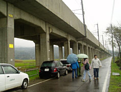
In this section of Shinkansen viaducts, the main structure was the multi-span reinforced concrete rigid-frame structure with reinforced concrete pile foundations of 16 m in length. There were two types of rigid-frame viaduct, including gerber type and divided-pillar type as shown in Fig. 1. The height of columns varies with route elevation and ground level.

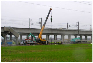
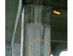
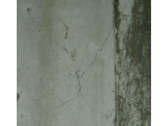
The rigid-frame viaducts located between the north entrance of tunnel and the location where derailed train stopped suffered damage. Damage mainly occurred at top of the columns in rigid-frame viaducts, i.e. underneath the rigid-zone of connection of beam and column. The damage included flexural crack, spalling of cover concrete, flexural failure with extensive spalling of cover concrete and exposure of reinforcements as shown in Photos 2, as well as shear cracks at column midheight, which developed from the flexural crack, as shown in Photo 3.

Photo 1 Location of derailed Shinkansen train
(a) gerber type
(b) divided-pillar type.
Fig. 1 Rigid-frame viaducts

It is noted that damage concentrated on the corner of columns, which resulted from the bi-directional excitation effect and damage occurred in the transverse direction at some locations. Mostly end columns suffered extensive damage than interior columns, especially in the gerber-type rigid-frame viaducts. It may be attributed to the difference of beam-column joints at the end columns and the interior columns. In order to support the gerber deck, an end beam with bracket has larger section than an interior beam in the transverse direction so that the constraint of an end column is stiffer than that of an interior column. In addition, horizontal cracks were observed at the end floor beam in girder viaduct. No obvious damage was observed in the rigid-frame bridges with double-layer beams. Also, there is no obvious damage between the location where derailed train stopped and Nagaoka station.
Photo 2 Rigid-frame viaduct

(a)Shear cracks in a column
(b) Detail
Photo 3 Shear Cracks


Footer